Sunday, April 7, 2013

Experiment 8: Concave and Convex Mirrors

PURPOSE: The purpose of the experiment was to see the images with the use of both a convex and a concave mirror. Using these mirrors the magnification and the how the image is displayed was observed to verify the effects of both a convex and concave mirror.

PROCEDURE:

Convex Mirror


Concave Mirror


Observing the effects on an image for both the concave and convex mirrors

Verifying if the image is being inverted or staying erect.
Concave-inverted
Convex-erect

Observation of the magnification in a Concave mirror


Observation of the magnification in a Convex Mirror

DATA and ANALYSIS:

Convex Mirror


Concave Mirror

Ray Diagram Concave Mirror

Ray Diagram Convex Mirror


CONCLUSION:

In the experimental observation, the convex mirror displayed images that were smaller than the original object and showed the image upright. As the object moved farther away the image became even smaller and larger when closer to the mirror. The image is considered a virtual image however since the rays as shown in the diagrams, did not pass through the image. Therefore convex mirrors displays a virtual image that is upright and is magnified smaller.

The observations for the concave mirror were somewhat different. Referring to the diagram of the concave mirror, as the object distance is larger, the image becomes inverted. When the object distance is just the same as the radius of curvature, C, both the object distance and image distance are the same. The image would not show if the distance was the same as the focal length. If the object was less than the focal length the image would be considered virtual and erect since the rays did not pass through the image. 

The magnification verifies the experiment by the showing of signs proving if the image was inverted or virtual. Based on the data, the observations and the magnification calculations both agree within terms and explains the phenomena between concave and convex mirrors. 

Friday, April 5, 2013

Experiment 9: Lenses

PURPOSE: To observe and verify the relationship between the object distance and the image distance through a mathematical relationship.


PROCEDURE:
Convex lens used in the apparatus for the experiment 


Setup of the apparatus with convex lens between the object and the image projection.

Image of the object displayed at some distance from the lens


image displayed inside the lens when object is 0.5f  from the lens.


DATA & ANALYSIS:

Focal point was determined to being 5.3 cm for the lens.

Focal distance
Object Distance cm
Image Distance cm
Object Height cm
Image Height cm
Magnification
Type of Image
5f
26.5 ± 0.3
7 ± 0.3
8.8 ± 0.1
2.3 ± 0.05
0.261363636
Diminished;Inverted; real
4f
21.2 ± 0.3
7.7 ± 0.3
8.8 ± 0.1
2.9 ± 0.05
0.329545455
Diminished;Inverted; real
3f
15.9 ± 0.3
8.4 ± 0.3
8.8 ± 0.1
4.6 ± 0.05
0.522727273
Diminished;Inverted; real
2f
10.6 ± 0.3
11.5 ± 0.3
8.8 ± 0.1
9.1 ± 0.05
1.034090909
Same; Inverted; real
1.5f
7.95 ± 0.3
15.95 ± 0.3
8.8 ± 0.1
16 ± 0.05
1.818181818
Magnified;Inverted; real

If the object distance was set to 0.5f the image no longer appears on the screen and instead is displayed on the lens itself and is also no longer inverted and instead erect. The image is therefore considered virtual since it is displayed on the object side.


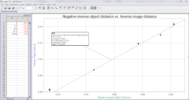
With the best fit line an equation, y= mx+b is found with a slope of .9038 and a y-intercept 0.1748. The y intercept is the inverse of the focal length.

Measured focal length
Y-intercept focal length
5.3 cm ± 0.5
5.72 cm 


CONCLUSION:

The magnification had increased as the focal distance decreased until the object was less than the focal distance which created a a virtual image and thus did not show up as a projection on the piece of paper.          
The lens used was a converging lens inverting the image onto the piece of paper creating a real image of the object. However, again the image was erect in the lens when the object distance was .5f, creating a virtual image. Graph 1 shows the relationship between the image and the object distance verifying that there was an inverse relationship. Graph 2 represented a different approach to view the relationship between the object distance and the image distance. A negative inverse and and inverse image distance was graphed and the y-intercept that was found from the linear graph equaled to the inverse of the focus length. The measured focal length that was used by the suns ray was about 5.3 with an uncertainty of about ± 0.5. With this uncertainty the y-intercept or focal length is within the value of uncertainty indicating that the relationship between the image distance and object distance is verified with the following equation